Specifications
Voltage Designations |
N/A 480 VAC 50/60 Hz |
Load |
N/A 70 AMPS |
Output Voltage |
N/A 0 to 97% of Input Voltage Phase Angle |
Control Signal (CP Phase Angle) |
N/A 4 to 20 mA at 1.5 volts DC per zone |
Input Impedance |
N/A 75 ohms per zone |
Linearity |
N/A Less than 15% deviation |
Response Time |
N/A 12 mS (STD unit, non soft start) |
Thermostat |
N/A 190 ºF (fan cooled units only) |
Power Dissipation (Watts) |
N/A 1.2 x maximum current |
Zone Designations |
N/A 2 |
Method of Firing |
N/A P-Phase Angle Fired |
Ordering Note |
N/A 150-1200 Amp units only available in 2 or 3 legs. |
Phase Angle Options
Soft Start |
N/A S-3 Seconds S02-2 Seconds |
Current Limit |
N/A CL- Current Limit CLP-Current Limit with Panel Mount Potentiometer |
Voltage Limit |
N/A VL-Standard 1 Turn PCB VL25-25 Turn PCB |
3-Phase Control Options
|
3-leg phase angle fired, A3P style, add “3P” to part number. |
Warranty
|
All Avatar Instruments products carry a full five year, warranty from date of purchase, parts and labor warranty against component failure and defects in workmanship . In the event your controller fails to perform properly, contact Avatar to obtain a return authorization number. Controllers sent to Avatar for warranty service that have no apparent defect will be treated as a standard repair and a $50.00 charge will be applied. Avatar will repair or replace any unit that failed due to defective parts or assembly. This warranty DOES NOT cover damage due to shipping, abuse, misapplication or operation beyond specified rating. Further more fuses and improperly fused SCR's are NOT COVERED by this warranty. Avatar is not responsible for any subsequent or other damage experienced in use of this device. |
Capabilities
Features |
N/A
|
Theory of Operation |
N/A
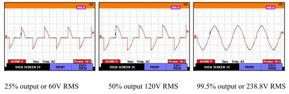 PHASE ANGLE FIRED (2CP – 8CP) These controls proportionally turn on a percentage of each power line half cycle. This gives smooth, infinitely variable application of power to the heaters. Imagine a light dimmer and how it provides power to The standard input signal (4-20 mA) is applied to the blue input terminal block, processed and fed to an optical coupler. The output of the optocoupler feeds the drive circuitry which is then fed to a pair of inversely connected SCR's. Additionally, an MOV (metal oxide varistor) is connected in parallel with the SCR's, providing voltage spike protection to the controller. |